ppboards - shields for the DE10-Nano board
ppboards are shields that plug into the two 40-pin 2.54 mm GPIO pin headers on the DE10-Nano board.
They enable custom interfaces to the DE10-Nano SoC FPGA. As an example, a KiCad design for
a simple shield using Pmod-style expansion connectors is provided (PP_PMOD, described below). This reference design
can be used as is or it can serve as a starting point for derivative designs (different connectors, buffering, etc.).
For exact GPIO header pinouts and electrical limits, verify against the Terasic board documentation before designing or assembling a shield.
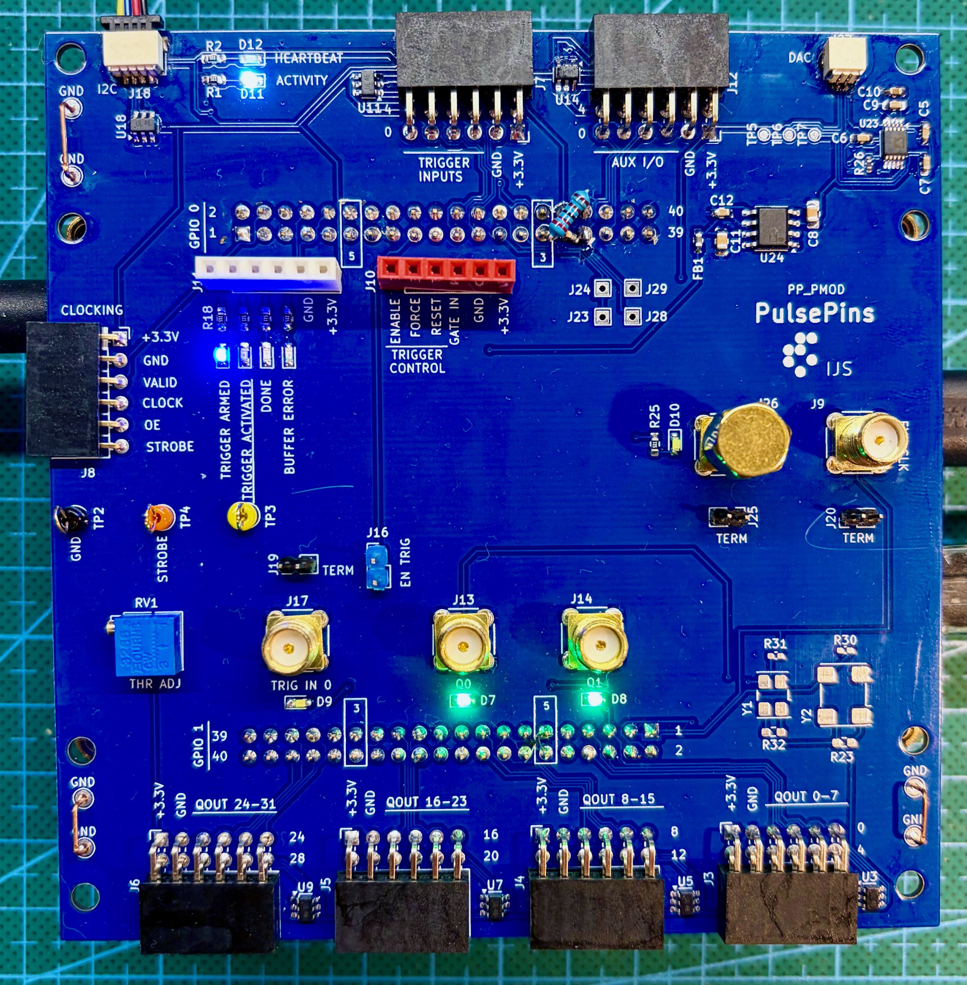
PP_PMOD
This PulsePins shield board provides output signals broken out on four dual Pmod-style ports carrying 8 bits each. In addition, the board has expansion connectors for trigger inputs and AUX signals, separate header breakouts for trigger control and status, and dedicated SMA connectors for clocking and instrument hookup. Other features:
- all signals on connectors have ESD protection diodes
- SMA connectors for external clock and for pulse-per-second (PPS) signals; monitoring LED for PPS signal; optional built-in 50 Ω terminators (enabled by jumpers)
- SMA connector for one trigger signal; it is connected to a fast comparator with a tunable threshold voltage; optional 50 Ω terminator; monitoring LED
- two buffered output signals are wired to SMA connectors; monitoring LEDs
- Status LEDs: trigger armed, trigger activated, done, buffer error
- Activity & heartbeat LEDs
- Qwiic I2C connector for external modules
- Optional onboard
MCP9808temperature monitor (I2C interface) - Optional 16-bit DAC (I2C interface) with separate low-noise power supply (a possible application is frequency tuning of an OCXO; with PPS from a GNSS receiver, PulsePins can serve as a simple GPS-disciplined oscillator)
- Footprints for optional CMOS oscillator modules for clocking the PulsePins system
- Test points for troubleshooting
- GND connection bars for grounding oscilloscope probes
Detailed board documentation:
KiCad schematics and PCB layouts, as well as the Gerber files for producing the boards, are available on the GitHub repository.