Sequencer model
PulsePins turns compact sequence elements into deterministic digital output updates. This page describes the model shared by the command-line tools, C++ and Python APIs, and FPGA streamer.
For the RTL implementation, register map, and clock-domain details, continue with the Streamer subsystem, Implementation details, and Clock domains.
Data path and run-length encoding
Run-length encoding (RLE) stores a stable output value as a value and a repetition count instead of recording one sample per clock. A regular element with count N holds its output value for N streamer-clock cycles.
The HPS sends encoded elements through an Avalon-ST input path. The FPGA classifies and decodes those elements, crosses the decoded updates into streamer_clk through an output FIFO, and advances the output after the configured trigger fires and while the gate is open. The readback path can encode the emitted samples again for verification or capture.
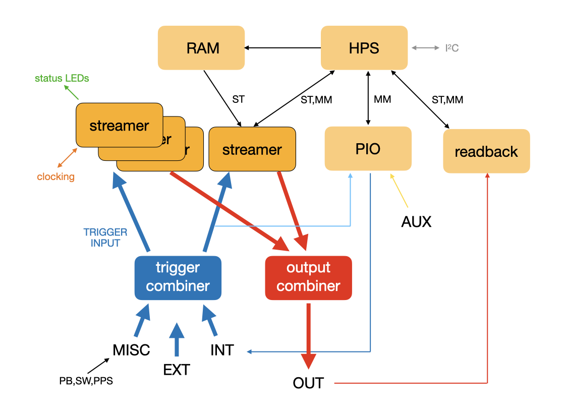
HPS means hard processor system (ARM cores), ST means Avalon-ST, MM means Avalon-MM, and PIO means programmable input/output.
Sequence elements
Each element contains three 32-bit values in the released DE10-Nano build:
control_t y: control parametercount_t c: run length, replay count, or other count payloadvalue_t v: output value, replay length, or packed trigger payload
The standard transport order is control, count, value. Matching RTL and software builds can use different data or count widths.
The user-facing PulsePins text sequence format represents a normalized subset of this model rather than arbitrary raw element triplets.
The control parameter is defined in ip/streamer/config.vh:
| Name | Bit | Meaning |
|---|---|---|
BIT_TRIGGER |
0 | regular element (0) or trigger element (1) |
BIT_TRIGGER_FINAL |
1 | intermediate or final trigger stage |
BIT_TERMINATE |
2 | sequence terminator |
BIT_NO_STROBE |
3 | suppress qout_valid and qout_strobe |
BIT_MODE* |
4-7 | load, set, clear, flip, invert, shift, and other update modes |
BIT_NOPASS |
8 | pass directly or send through the preprocessor |
BIT_STORE |
9 | store an element in preprocessor memory |
BIT_POSITIONS* |
10-12 | preprocessor storage position in the released eight-slot build |
BIT_REPLAY |
15 | replay a stored subsequence |
BIT_RETRIG |
16 | request the next trigger subsequence |
BIT_PRNG |
17 | emit pseudorandom values |
Regular and final elements
A regular element specifies an output update and how long the resulting state persists. The mode bits can load a complete value or apply an operation such as set, clear, toggle, shift, AND, OR, XOR, or XNOR.
Normally a regular element asserts qout_valid and produces a qout_strobe pulse. BIT_NO_STROBE suppresses those qualifiers but still updates the output bus.
The final element terminates decoding and leaves its decoded value as the persistent final state. On a clean run, consuming the terminator asserts done. A final element is not reported as an ordinary valid output sample.
Trigger elements
Trigger elements travel through the same input stream but are loaded into the trigger-program path rather than the normal output decoder. Each stage contains a mask and a pattern. A mask bit selects an input to test, and the corresponding pattern bit specifies the required value.
For the released 8-bit trigger bus, a trigger element sets c to zero and packs both fields into v: bits 7:0 hold the pattern and bits 15:8 hold the mask.
The released trigger-program buffer has 256 positions. A chain fires after its stages have matched in order and a final trigger stage has been reached, or after the loaded chain is exhausted.
A sequence that uses retriggering must mark the last trigger element of each trigger subsequence as final. That marker separates the trigger stages consumed before one output segment from those loaded after the retrigger element.
Replay preprocessor
The input preprocessor provides a second level of compression. It can store up to eight elements in the released build and replay that short subsequence without sending every repetition from the HPS.
A replay count of zero repeats indefinitely. This is the mechanism used by tools such as ppfg for continuous periodic output.
Sequence delivery
PulsePins has two main delivery paths:
- HPS-driven FIFO streaming for normal interactive and generated sequences
- memory-backed DMA transfers for sequences up to 512 MB
Both paths feed the same encoded streamer model. DMA avoids HPS intervention during the transfer and is useful when quickly changing output data could exhaust the software-fed FIFO path. After output consumption has started, the output FIFO latches buffer_error if advancement is requested before more data or the terminator is available. Empty reads during initial FIFO priming are not treated as underruns.
Multiple streamers and output routing
The released design contains four independent streamer instances with separate trigger programs. Their outputs feed a configurable combiner before reaching the physical output bus.
The combiner supports:
- selection of one streamer
- bitwise AND, OR, XOR, and XNOR
- per-bit majority voting
- 8-bit and 16-bit block concatenation
- sums and differences
- per-input and final-output masks, inversion, and forced values
See the Combiner subsystem for mode definitions, register behavior, and software control.
Trigger, gate, and retrigger behavior
The trigger combiner can select or combine internal software signals, external trigger pins, and miscellaneous board signals such as push-buttons, switches, and PPS. Trigger matching is active only while trigger enable is asserted. Trigger force bypasses normal mask/pattern matching.
The main runtime controls have distinct purposes:
| Control | Effect | Resume behavior |
|---|---|---|
| gate | pauses output FIFO advancement without changing trigger state | reopen the gate |
| stop | halts advancement while preserving the current stream position | clear stop if the stream remains valid |
| trigger reset | deactivates and re-arms the same active trigger stage; queued stages remain loaded | release reset and satisfy or force that stage again |
| retrigger element | completes the current trigger subsequence and waits for the next queued one | satisfy or force the next trigger stage |
| streamer reset | clears streamer and trigger FIFO state | load a new sequence |
Holding trigger reset asserted prevents triggering, including a forced trigger. None of gate, stop, or trigger reset forces qout to a safe value; the bus holds its last state until another element, override, or streamer reset changes it.
See Streamer timing diagrams for trigger, gate, and retrigger waveforms, and pptrig for source-selection diagnostics.
Clocks and output timing
The main clocks are the 50 MHz board reference ref_clk, the control-side core_clk, the internal candidate output clock int_clk, and the selected streamer_clk. The released image normally uses 100 MHz for core_clk and streamer_clk, giving a 10 ns programmable output time step.
Decoded updates cross from the control side into streamer_clk through a dual-clock FIFO. qout updates on rising edges of streamer_clk; qout_valid qualifies ordinary output samples, and qout_strobe appears during the low phase of streamer_clk. Use one of those qualifiers to detect advancement because qout can hold its previous value while a gate is closed.
The selected streamer_clk must run continuously: output advancement, trigger state, reset synchronization, and completion all depend on it. When using an external source, establish a stable clock before selecting that path and keep it running through reset and shutdown handling.
Sampling qout on rising streamer_clk edges while qout_valid is high gives the receiver the normal clocked-data relationship and is preferred at higher rates. qout_strobe can be convenient for slower logic that needs additional hold time after the rising clock edge, but its board-level timing should be verified for the actual receiver and cabling.
The active output clock can be selected from the internal clock path or an external 3.3 V LVTTL source on EXT_CLKp. See Clock domains, RTL latency and timing, and Streamer timing diagrams before relying on cycle-level behavior.
Output enable and readback
The 32 main output drivers default to high impedance. Setting the physical output enable oe lets the final combined qout value drive the pins. With oe low, the pins can instead be sampled by the readback and counter paths. The same output enable controls the bidirectional qout_valid and qout_strobe pads used by the external-capture path.
The Readback subsystem re-encodes qout_valid-qualified samples for self-test and capture. Replay of a readback export reproduces those normalized runs rather than recovering authored operators, control flow, no-strobe states, or elapsed invalid gaps. General C++ VCD export is a flattened regular-record projection with additional fidelity limits.
Configurable variants
The RTL and software are structured for matching data and count widths other than 32 bits. PulsePins has been extended to 64 output channels and 64-bit counts, although only the 32-bit data/count DE10-Nano design is distributed as a prebuilt image.
The design has also been ported to an Arria 10 platform for driving 10 Gb/s transceivers on a Terasic HAN Pilot, corresponding to a 100 ps unit interval. These variants require matching RTL, generated hardware, and software builds.